
DTC P0031 HO2S HEATER CONTROL CIRCUIT LOW (BANK 1 SENSOR 1)
| DTC P0031 HO2S HEATER CONTROL CIRCUIT LOW (BANK 1 SENSOR 1) |
DTC DETECTING CONDITION:
| • |
Immediately at fault recognition
|
|
| • |
GENERAL DESCRIPTION

|
|
| Important | ||
|
After repair
or replacement of faulty parts, conduct Clear Memory Mode
|
||
WIRING DIAGRAM:
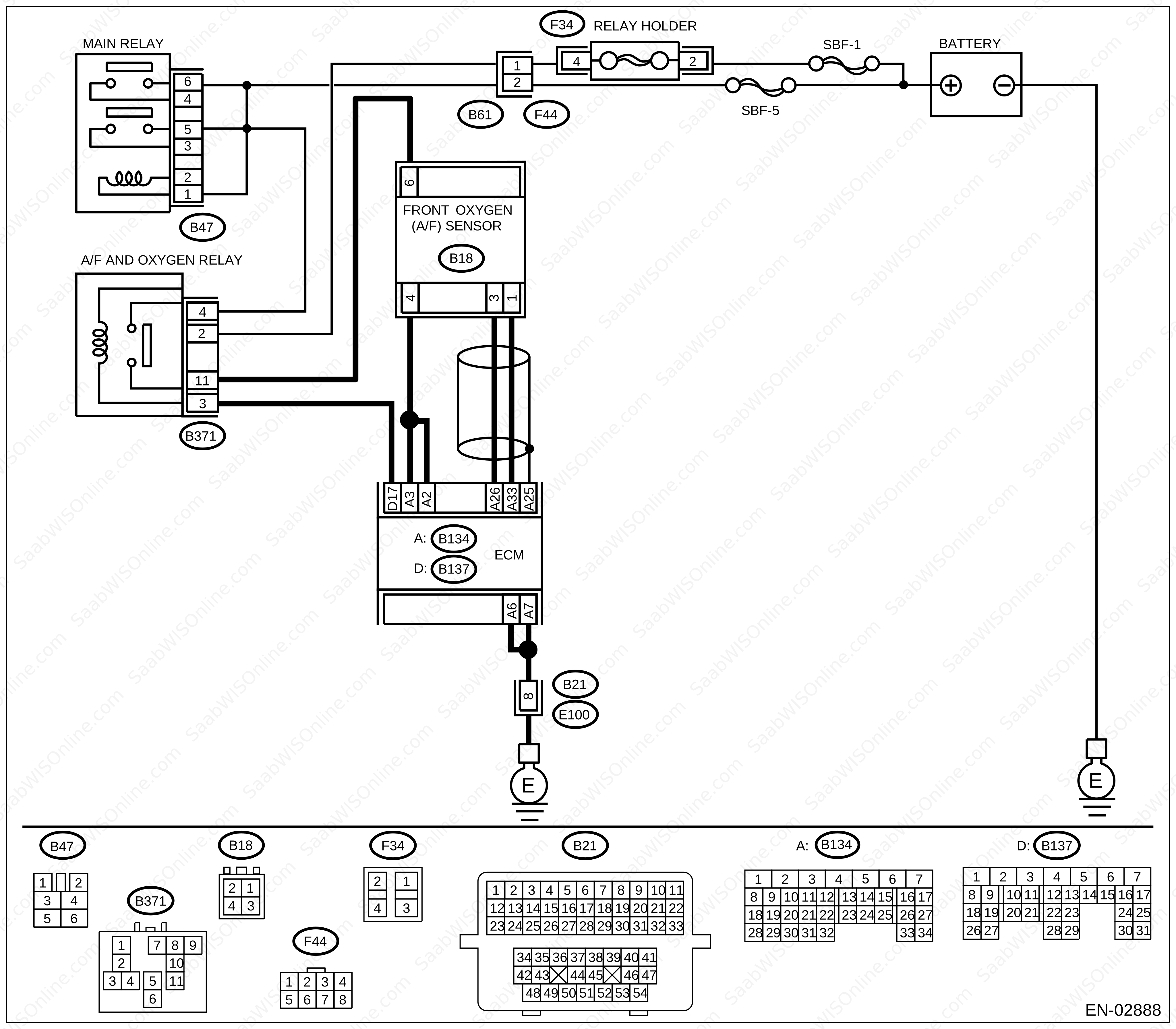
CHECK ANY OTHER DTC ON DISPLAY.
Does the Vehicle Diagnostic Interface or OBD-II general scan tool display DTC P0031 and P0037 at the same time?
| Yes |
| No |
CHECK POWER SUPPLY TO FRONT OXYGEN (A/F) SENSOR.
Turn the ignition switch to OFF.Disconnect the connector from front oxygen (A/F) sensor.
Turn the ignition switch to ON.
Measure the voltage between front oxygen (A/F) sensor connector and engine ground.
Connector & terminal
(B18) No. 6 (+) — Engine ground (−):
Is the voltage more than 10 V?
| Yes |
| No |
| • |
Repair power supply line.
|
|
| • |
|
||||||||||||||||
CHECK GROUND CIRCUIT OF ECM.
Measure the resistance of harness between ECM connector and chassis ground.Connector & terminal
(B134) No. 7 — Chassis ground:
(B134) No. 6 — Chassis ground:
Is the resistance less than 5 Ω?
| Yes |
| No |
| • |
Repair harness and connector.
|
|
| • |
|
|||||||||||||
CHECK CURRENT DATA.
Start the engine.Read the data of front oxygen (A/F) sensor heater current using Vehicle Diagnostic Interface or OBD-II general scan tool.
| Note | ||
| • |
Vehicle Diagnostic Interface
For detailed operation procedure, refer to the “READ
CURRENT DATA FOR ENGINE”.
|
|
| • |
OBD-II scan tool
For detailed operation procedures, refer to the OBD-II General Scan Tool Instruction Manual. |
|
Is the current more than 0.2 A?
| Yes |
| • |
Repair poor contact in connector.
|
|
| • |
|
|||||||||||||
| No |
CHECK INPUT SIGNAL FROM ECM.
Start and idle the engine.Measure the voltage between ECM connector and chassis ground.
Connector & terminal
(B134) No. 3 (+) — Chassis ground (−):
(B134) No. 2 (+) — Chassis ground (−):
Is the voltage less than 1 V?
| Yes |
| No |
CHECK OUTPUT SIGNAL FROM ECM.
Measure the voltage between ECM connector and chassis ground.Connector & terminal
(B134) No. 3 (+) — Chassis ground (−):
(B134) No. 2 (+) — Chassis ground (−):
Does the voltage change by shaking the ECM harness and connector?
| Yes |
Repair poor contact in ECM connector.
| No |
CHECK FRONT OXYGEN (A/F) SENSOR.
Turn the ignition switch to OFF.Measure the resistance between front oxygen (A/F) sensor connector terminals.
Terminals
No. 4 — No. 6:
Is the resistance less than 10 Ω?
| Yes |
| • |
Repair harness and connector.
|
|
| • |
|
||||||||||||||||
| No |
Replace the front oxygen (A/F)
sensor.
This project is supported by memberships and donations. If you use this site, please consider Joining SCNA and/or making a donation.
Our Friends