DTC P0691 COOLING FAN 1 CONTROL CIRCUIT LOW
| DTC P0691 COOLING FAN 1 CONTROL CIRCUIT LOW |
DTC DETECTING CONDITION:
| • |
Two consecutive driving cycles with fault
|
|
| • |
GENERAL DESCRIPTION

|
|
TROUBLE SYMPTOM:
| • |
Radiator fan does not operate properly.
|
|
| • |
Overheating
|
|
| Important | ||
|
After repair
or replacement of faulty parts, conduct Clear Memory Mode
|
||
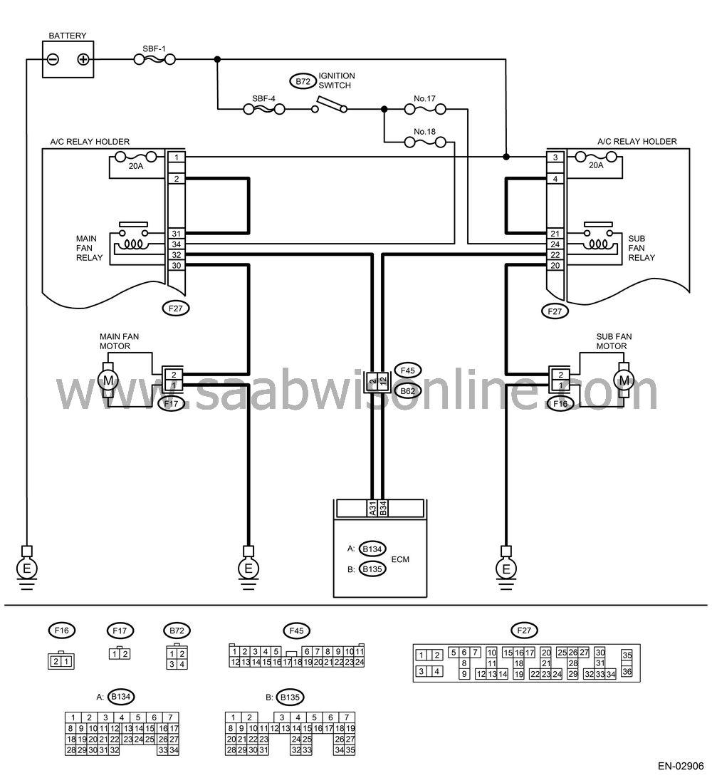
WIRING DIAGRAM:

CHECK OUTPUT SIGNAL FROM ECM.
Turn the ignition switch to OFF.Connect the test mode connector at the lower portion of instrument panel (on the driver’s side).
Turn the ignition switch to ON.
While operating the radiator fan relay, measure voltage between ECM terminal and ground.
| Note | ||
|
Radiator fan relay operation can
be executed using Vehicle Diagnostic
Interface. For procedure, refer to “Compulsory Valve Operation
Check Mode”.
|
Connector & terminal
(B135) No. 34 (+) — Chassis ground (−):
(B134) No. 31 (+) — Chassis ground (−):
Is the voltage 0 — 10 V?
| Yes |
Repair poor contact in ECM connector.
| No |
CHECK GROUND SHORT CIRCUIT IN RADIATOR FAN RELAY CONTROL CIRCUIT.
Turn the ignition switch to OFF.Disconnect the connectors from ECM.
Measure the resistance of harness between ECM connector and chassis ground.
Connector & terminal
(B135) No. 34 — Chassis ground:
(B134) No. 31 — Chassis ground:
Is the resistance less than 10 Ω?
| Yes |
Repair ground short circuit in radiator fan relay control circuit.
| No |
CHECK POWER SUPPLY FOR RELAY.
Remove the radiator fan relay from A/C relay holder.Turn the ignition switch to ON.
Measure the voltage between fuse and relay box (F/B) connector and chassis ground.
Connector & terminal
(F27) No. 24 (+) — Chassis ground (−):
(F27) No. 34 (+) — Chassis ground (−):
Is the voltage more than 10 V?
| Yes |
| No |
Repair open circuit in harness between ignition switch and fuse and relay box (F/B) connector.
CHECK RADIATOR FAN RELAY.
Turn the ignition switch to OFF.Measure the resistance between radiator fan relay terminals.
Terminals
No. 22 — No. 24:
No. 32 — No. 34:
Is the resistance 87 — 107 Ω?
| Yes |
| No |
Replace the radiator fan relay.
CHECK OPEN CIRCUIT IN RADIATOR FAN RELAY CONTROL CIRCUIT.
Measure the resistance of harness between ECM and radiator fan relay connector.Connector & terminal
(B134) No. 31 — (F27) No. 32:
(B135) No. 34 — (F27) No. 22:
Is the resistance less than 1 Ω?
| Yes |
| No |
| • |
Repair harness and connector.
|
|
| • |
|
|||||||||||||
CHECK POOR CONTACT.
Check poor contact in ECM or radiator fan relay connector.Is there poor contact in ECM or radiator fan relay connector?
| Yes |
Repair poor contact in ECM or radiator fan relay connector.
| No |
Contact Service Center.


