Grinding (turning) a brake disc, in situ
| Grinding (turning) a brake disc, in situ |
Lathe “VBG 600” and the SAAB/GM 108/4--110/5 connecting plate were used in the development of this method.
| 1. |
Raise the car and remove the wheels on both sides.
|
||||||||||
| 2. |
If the work is carried out in the order front right, front left, rear left, rear right, then basic adjustment of the lathe will be facilitated.
|
|
| 3. |
Remove the brake caliper without remove the brake line. Suspend the caliper with a cable tie. Refer to
To remove
for the front wheels and
To remove
for the rear wheels.
|
|
| 4. |
Measure the disc. Refer to
Checking for lateral runout and variation in thickness, front wheels
and
Checking for lateral runout and variation in thickness, rear wheels
.

|
|
| 5. |
Clean the mating surface between the brake disc and the connecting plate.
|
|
| 6. |
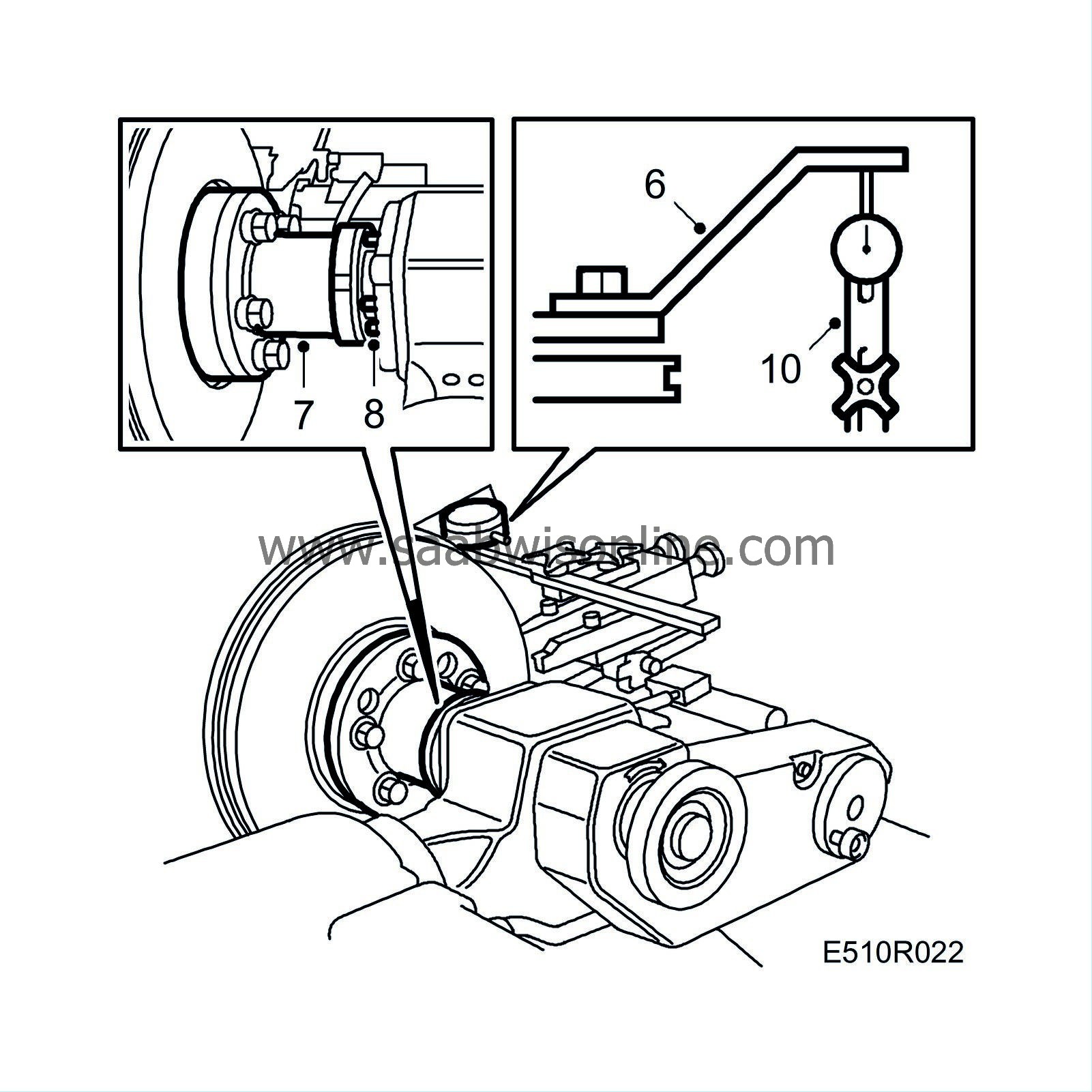
Fit the tool for runout compensation (accessory 25) in the brake caliper bracket.
|
|
| 7. |
Fit the connecting plate with the wheel studs.
Tightening torque: 30 Nm (22 lbf ft). |
|
| 8. |
Back off the adjusting screws.
|
|
| 9. |
Clean the connecting surface and fit the lathe to the connecting plate, connect the lathe.
|
|
| 10. |
Connect the arm with the dial gauge resting against the runout compensation tool.
|
|
| 11. |
Start the lathe and note the highest and lowest readings. Switch off the lathe.
|
|
| 12. |
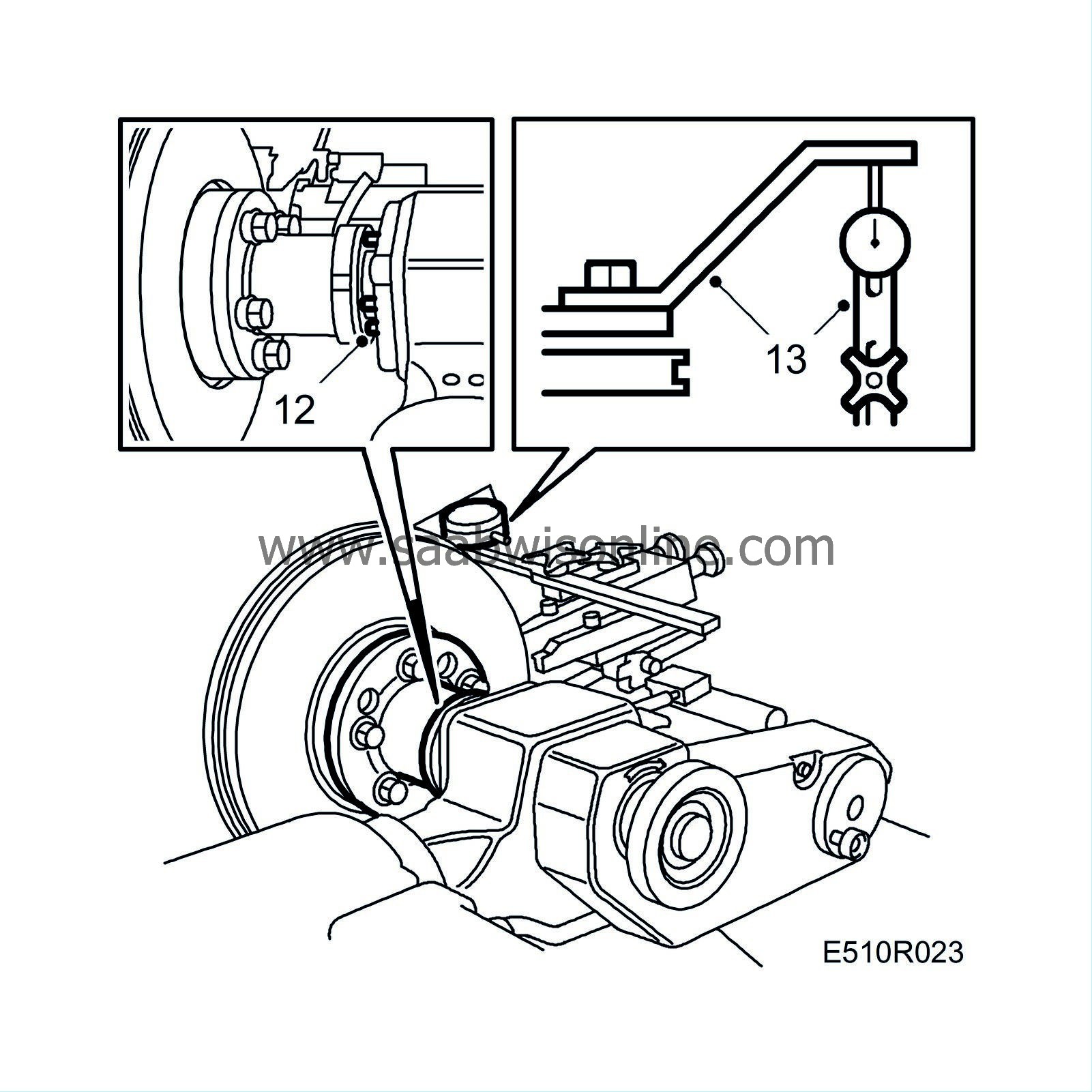
Adjust one of the four adjusting screws and repeat points 9 and 10 until the variation is less than 0.08 mm (0.003 in).

|
|
| 13. |
Remove the arm with dial gauge and the runout compensation tool.
|
|
| 14. |
Adjust the turning tools against the disc with the tool holder. Remove the locking screw and move the holder.

|
|
| 15. |
Set the automatic stop.
|
|
| 16. |
Feed out the tool holder and manually grind off the outer and inner rusty edges.
|
|
| 17. |
Set the turning depth and switch on automatic operation.
|
|
| 18. |
Check the brake disc.
|
|
| 19. |
Remove the lathe. Remove the connecting plate.
|
|
| 20. |
Fit the brake caliper. Refer to
To fit
for the front wheels and
To fit
for the rear wheels.
|
|
| 21. |
To grind (turn) the other side, the lathe will have to be turned upside down.

|
|
| 22. |
Grinding (turning) is then carried out as described above.
|
|


