Transfer Case Assembly Replacement
| Transfer Case Assembly Replacement |
| Special Tools |
DT-48783 Special Adjustable Socket E18 Extended
For equivalent regional tools, refer to Special Tools .
| Removal Procedure |
| 1. |
Remove the propeller shaft. Refer to
Propeller Shaft Replacement
.
|
|
| 2. |
Manual transmission: Drain the transmission fluid. Refer to
Transmission Fluid Replacement
.
|
|
| 3. |
Automatic transmission: Drain the transmission fluid. Refer to
Transmission Fluid Level and Condition Check
.
|
|
| 4. |
Release the right drive shaft. Refer to
Front Wheel Drive Shaft Replacement - Right Side (GNB)
Front Wheel Drive Shaft Replacement - Right Side (Petrol)
.
|
|
| 5. |
Remove the front wheelhouse front liner. Refer to
Front Wheelhouse Front Liner Replacement
.
|
|
| 6. |
Remove the subframe. Refer to
Drivetrain and Front Suspension Frame Front Crossmember Replacement (GNA)
Drivetrain and Front Suspension Frame Front Crossmember Replacement (GNB)
.
|
|
| 7. |
Remove the transmission rear mount bracket. Refer to
Transmission Rear Mount Replacement
.
|
|
| 8. |
Remove the bleed hose, if equipped.
|
|
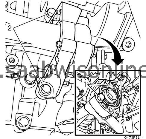
| 9. |
Remove the support bracket fasteners (1).
|
|
| 10. |
Remove the support bracket to engine fasteners (2).
|
|
| 11. |
Support the transfer case with a column jack, and secure with cable ties.
|
|
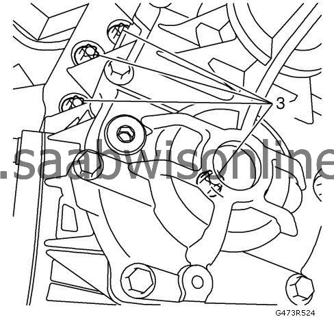
| 12. |
Remove the transfer case fasteners (3) using
special socket
DT-48783.
|
|
| 13. |
Lower and ease out the transfer case.
|
|
| Installation Procedure |
| 1. |
Clean the contact surfaces between the transfer case and the gearbox. Fit a new O-ring.
|
|
| 2. |
Raise and align the transfer case in the correct position in relation to the gearbox.
|
|
| 3. |
Refer to
Fastener Caution
.
Fit the transfer case. Tighten the bolts in the correct order as illustrated. Tighten110 Nm (81 lb ft)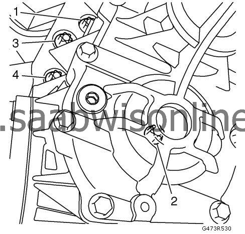
|
|
| 4. |
Fit the support bracket between the transfer case and the engine carefully in three steps to avoid breakage.
|
|
| 5. |
Tighten the support bracket fasteners (1).
Tighten5 Nm (44 lb in)
|
|
| 6. |
Tighten the support bracket to engine fasteners (2).
|
|
| • |
For LBW/A28NET:
22 Nm (16 lb ft)
|
| • |
For LDK/A20NHT and LBY/A20DTR:
60 Nm (44 lb ft)
|
| 7. |
Tighten the support bracket fasteners (1).
Tighten60 Nm (44 lb ft) |
|
| 8. |
Install the bleed hose, if equipped.
|
|
| 9. |
Install the transmission rear mount bracket. Refer to
Transmission Rear Mount Replacement
.
|
|
| 10. |
Install the subframe. Refer to
Drivetrain and Front Suspension Frame Front Crossmember Replacement (GNA)
Drivetrain and Front Suspension Frame Front Crossmember Replacement (GNB)
.
|
|
| 11. |
Install the front wheelhouse front liner. Refer to
Front Wheelhouse Front Liner Replacement
.
|
|
| 12. |
Install the right drive shaft. Refer to
Front Wheel Drive Shaft Replacement - Right Side (GNB)
Front Wheel Drive Shaft Replacement - Right Side (Petrol)
.
|
|
| 13. |
Install the propeller shaft. Refer to
Propeller Shaft Replacement
.
|
|
| 14. |
Manual transmission: Fill the transmission with oil. Refer to
Transmission Fluid Replacement
.
|
|
| 15. |
Automatic transmission: Fill the transmission with oil. Refer to
Transmission Fluid Level and Condition Check
.
|
|
This project is supported by memberships and donations. If you use this site, please consider Joining SCNA and/or making a donation.
Our Friends
