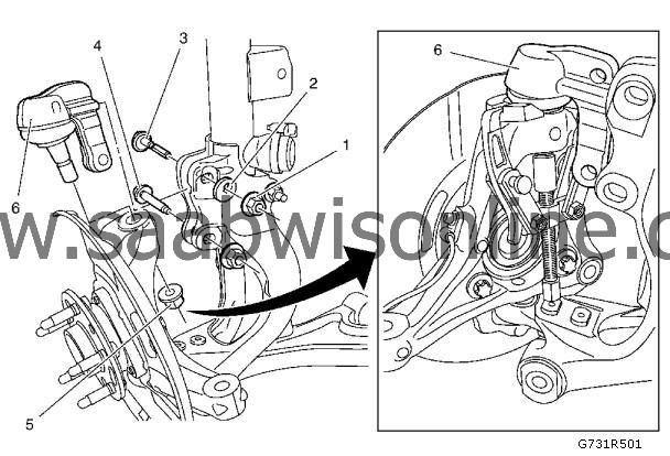
Steering Knuckle Upper Ball Stud Replacement (GNB)
|
|
Steering Knuckle Upper Ball Stud Replacement (GNB)
|

|
Callout
|
Component Name
|
Preliminary Procedure
|
1
|
Steering Knuckle Camber Adjust Nut
Refer to
Fastener Caution
.
Procedure
|
2.
|
After Installation check the front alignment and tighten the torque.
|
Tighten
70 Nm (52 lb ft) + 45 degrees + 15 degrees
|
2
|
Steering Knuckle Camber Adjust Washer
|
3
|
Steering Knuckle Camber Adjust Bolt
Procedure
Install NEW bolt.
|
4
|
Steering Knuckle Upper Ball Stud Fastener (Qty: 2)
Procedure
|
1.
|
Install NEW fasteners.
|
|
2.
|
After Installation check the front alignment and tighten the torque.
|
Tighten
115 Nm (85 lb ft) + 45 degrees + 15 degrees
|
5
|
Steering Knuckle Upper Ball Stud Nut
|
Note
|
|
Use
CH-49375
wrench to tighten the upper ball stud nut.
|
Tighten
45 Nm (33 lb ft) + 30 degrees + 15 degrees
Special Tools
CH-49375
Wrench
For equivalent regional tools. Refer to
Special Tools
.
|
6
|
Steering Knuckle Upper Ball Stud
Procedure
|
1.
|
Separate the steering knuckle upper ball stud from the strut yoke.
|
|
2.
|
Use the
CH-50094
ball joint remover and
DT-161-B
puller to remove the ball joint from the steering knuckle.
|
Special Tools
|
•
|
CH-50094
Ball Joint Remover
|
For equivalent regional tools. Refer to
Special Tools
.
|


