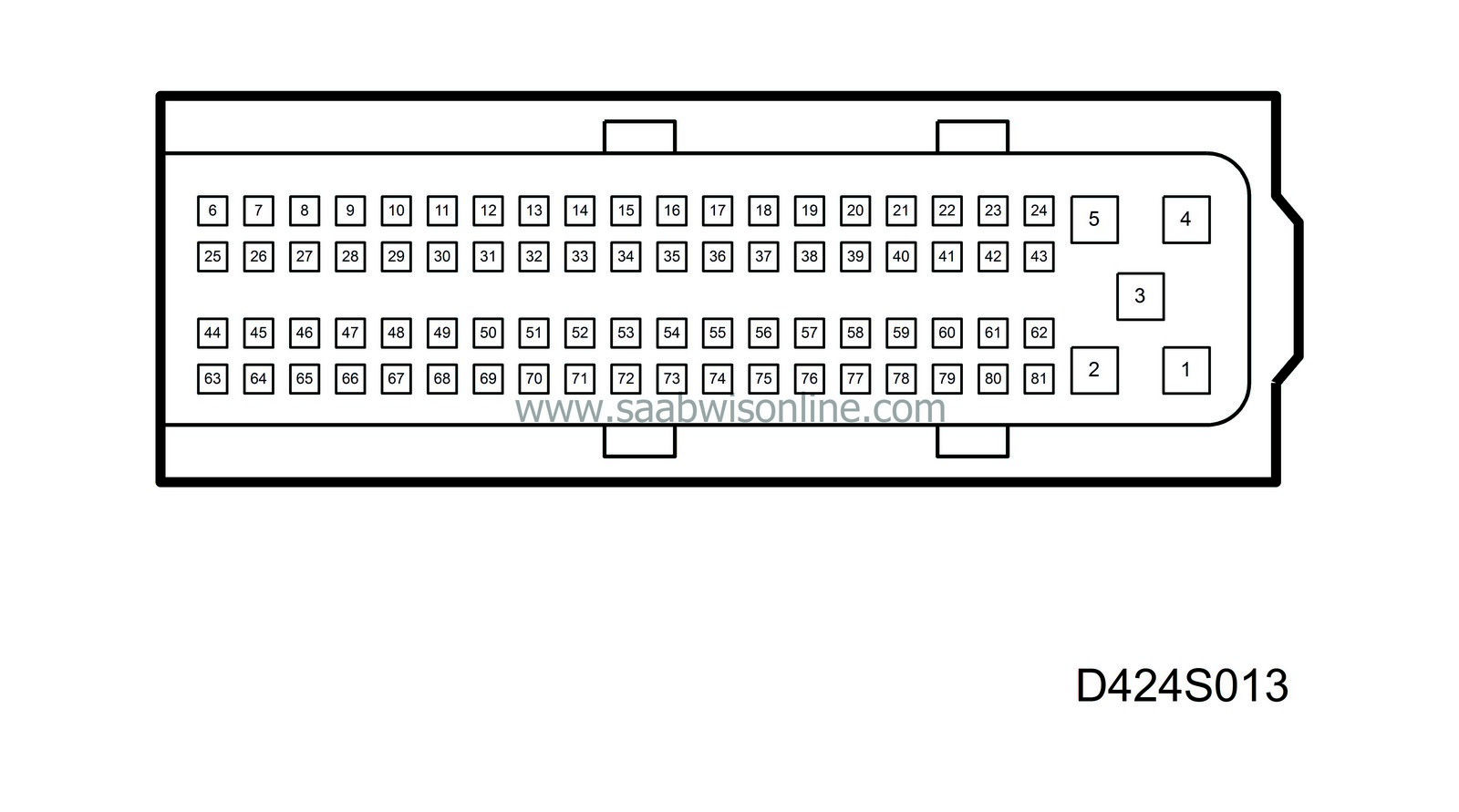
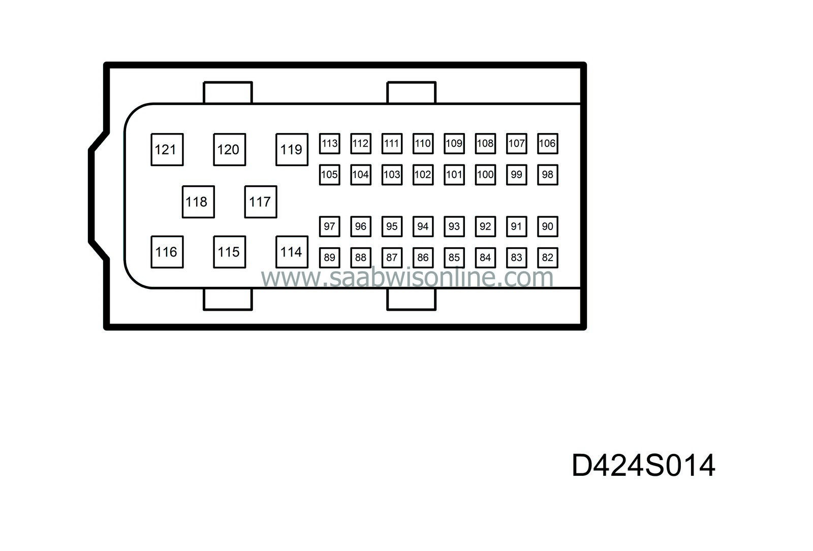
Pin
|
Colour
|
Component Function
|
In Out
|
Test conditions
|
Reading
|
Between X-Y
|
See
|
1
|
BK
|
Ground
|
In
|
|
B+
|
3 - 1
|

|
2
|
BK
|
Ground
|
In
|
|
B+
|
3 - 2
|

|
3
|
GN/RD
|
Power supply
|
In
|
Activate main relay
|
B+
|
3 - 1
|

|
30
|
VT
|
Brake light, signal
|
In
|
Ignition in ON position
Brake pedal depressed
Brake pedal released
|
B+
0 V
|
30 - 1
|

|
31
|
BK/GN
|
Clutch switch, signal
|
In
|
Ignition in ON position
Clutch pedal depressed
Clutch pedal released
|
B+
0 V
|
31 - 1
|

|
35
|
YE/BU
|
Data link K
|
IN/Out
|
|
10-11 V
|
35 - 1
|

|
38
|
BU
|
Accelerator pedal position sensor, signal
|
In
|
Idling speed
Wide open throttle
|
0.5 V
3.5 V
|
38 - 1
|

|
39
|
YE/GU
|
Power supply +15
|
In
|
Ignition in ON position
|
B+
|
39 - 1
|

|
41
|
RD/WH
|
Ground, A/C relay
|
In
|
Ignition in ON position
A/C relay activated
A/C relay not activated
|
0 V
B+
|
41 - 1
|

|
45
|
GN
|
Cruise control switch in OFF position
|
In
|
Ignition key in ON position, cruise control switch in OFF position
|
B+
|
45 - 1
|

|
49
|
YE
|
Accelerator pedal position sensor, ground
|
In
|
Ignition in ON position
|
<0.1 V
|
49 - 1
|

|
57
|
WH
|
Accelerator pedal position sensor, power supply
|
In
|
Ignition in ON position
|
5 V
|
57 - 1
|

|
58
|
BU/GY
|
Main relay, ground
|
Out
|
Ignition in ON position
|
<0.4 V
|
58 - 1
|

|
60
|
BN/YE
|
Control valve, swirl throttle
|
Out
|
Ignition in ON position
|
140 Hz (PWM)
|
60 - 1
|

|
63
|
GY/BK
|
Cruise control switch in RES/- position
|
In
|
Ignition key in ON position and cruise control switch in RES/- position
|
B+
|
63 - 1
|

|
64
|
GY/GN
|
Cruise control switch in SET/+ position
|
In
|
Ignition key in ON position and cruise control in SET/+ position.
|
B+
|
64 - 1
|

|
65
|
YE/GN
|
Brake light switch
|
In
|
Ignition in ON position
Brake pedal depressed
Brake pedal released
|
<0.1 V
B+
|
65 - 1
|

|
68
|
BK/VT
|
Speed signal
|
In
|
Rotating wheel (FR)
|
Square wave, frequency linear to speed
|
68 - 1
|

|
69
|
GY
|
Idling speed contact
|
In
|
Ignition key in ON position and accelerator released (idling speed)
|
3.7 V
|
69 - 1
|

|
82
|
GN/RD
|
Manifold absolute pressure sensor, power supply
|
Out
|
Ignition in ON position
|
5 V
|
82 - 1
|

|
83
|
BK
|
Mass air flow sensor, power supply
|
Out
|
Ignition in ON position
|
5 V
|
83 - 1
|

|
84
|
BK
|
Intake air temperature sensor
|
In
|
Ignition in ON position
|
0.3-4.7 V
|
84 - 1
|

|
85
|
BU/RD
|
Manifold absolute pressure sensor, signal
|
In
|
Ignition key in ON position, engine not running
|
2 V
|
85 - 1
|

|
86
|
BU
|
Engine oil temperature sensor
|
In
|
Ignition in ON position
|
0.3-4.7 V
|
86 - 1
|

|
87
|
YE
|
Glow duration feed-back, signal
|
In
|
Glow active
Glow inactive
|
0 V
B+
|
87 - 1
|

|
88
|
GN/WH
|
Mass air flow sensor, signal
|
In
|
Ignition in ON position
|
1.1 V
|
88 - 1
|

|
89
|
BU/YE
|
Coolant temperature sensor, engine management system, signal
|
In
|
Ignition in ON position
|
0.3-4.7 V
|
89 - 1
|

|
90
|
YE
|
Crankshaft position sensor, signal
|
In
|
Engine input, idling speed
|
60 Hz/900 rpm (sine wave)
|
90 - 1
|

|
91
|
RD/WH
|
Engine speed signal
|
Out
|
Engine input, idling speed
|
60 Hz/900 rpm (square wave)
|
91 - 1
|

|
92
|
BK
|
Mass air flow sensor, ground
|
In
|
Always
|
<0.2 V
|
92 - 1
|

|
93
|
BK
|
Sensor ground
|
In
|
|
<0.2 V
|
3 - 93
|

|
94
|
YE/WH
|
Control of glow function
|
Out
|
Glow active
|
0.2 V
|
94 - 1
|

|
96
|
GY/WH
|
Charge air control valve, power supply
|
Out
|
Ignition in ON position
|
140 Hz (PWM)
|
96 - 1
|

|
97
|
BU/WH
|
Control valve, exhaust gas recirculation, power supply
|
Out
|
Ignition in ON position
|
140 Hz (PWM)
|
97 - 1
|

|
98
|
BK
|
Crankshaft position sensor, ground
|
Out
|
|
<0.2 V
|
98 - 1
|

|
99
|
WH
|
P-bus -
|
In/Out
|
Ignition in ON position
|
2-3 V
|
99 - 1
|

|
100
|
GN
|
P-bus +
|
In/Out
|
Ignition in ON position
|
2-3 V
|
100 - 1
|

|
101
|
BK
|
Crankshaft position sensor, screen ground
|
In
|
|
<0.2 V
|
101 - 1
|

|
105
|
GN/YE
|
Control valve, shut-off signal
|
Out
|
When the engine has been turned off and the ignition key turned to OFF position
|
10 V
|
105 - 1
|

|


