Steering Knuckle King Pin Bushing Replacement (GNB)
| Steering Knuckle King Pin Bushing Replacement (GNB) |
| Removal Procedure |
Special Tools
Ch-49859-1 Puller Ch-49859-2 Guide pin| 1. |
Raise and support the vehicle. Refer to
Lifting and Jacking the Vehicle
.
|
|
| 2. |
Remove the tire and wheel assembly. Refer to
Tire and Wheel Removal and Installation
.
|
|
| 3. |
Separate the outer tie rod end from the knuckle. Refer to
Steering Linkage Outer Tie Rod Replacement
.
|
|
| 4. |
Remove the outer fastener from lower control arm. Refer to
Lower Control Arm Replacement (GNA)
Lower Control Arm Replacement (GNB)
.
|
|
| 5. |
Remove the front brake rotor. Refer to
Front Brake Rotor Replacement (J60, J61, J62)
Front Brake Rotor Replacement (J64)
.
|
|
| 6. |
Undo the wheel drive shaft from the wheel bearing/hub. Refer to
Front Wheel Drive Shaft Replacement - Left Side (GNA)
Front Wheel Drive Shaft Replacement - Left Side (GNB)
and
Front Wheel Drive Shaft Replacement - Right Side (GNB)
Front Wheel Drive Shaft Replacement - Right Side (Petrol)
.
|
|
| 7. |
Remove the front wheel speed sensor. Refer to
Front Wheel Speed Sensor Replacement (GNA)
Front Wheel Speed Sensor Replacement (GNB)
.
|
|
| 8. |
Separate the yoke from the suspension strut. Refer to
Strut Assembly Replacement (GNA)
Strut Assembly Replacement (GNB)
.
|
|
| 9. |
Remove the wheel bearing/hub. Refer to
Front Wheel Bearing and Hub Replacement (GNA)
Front Wheel Bearing and Hub Replacement (GNB)
.
|
|
| 10. |
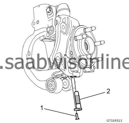
Remove the king pin fastener. (1)

|
|
| 11. |
Remove the king pin (2) using Ch-49859-1 Puller.

|
|
| 12. |
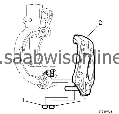
Remove the steering knuckle upper ball stud from knuckle. Refer to
Steering Knuckle Upper Ball Stud Replacement (GNB)
|
|
| 13. |
Remove nuts. (1)

|
|
| 14. |
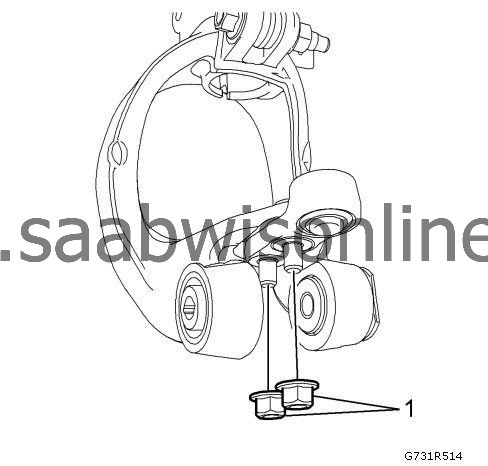
Remove bushing fasterners (1) using Ch-50093.

|
|
| 15. |
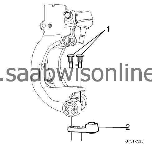
Remove steering knuckle king pin bushing (2)
|
|
| Installation Procedure |
| 1. |
Install bushing fasteners (1) using Ch-50093.

|
|
| 2. |
Install bushing (2) to fasterners using Ch-50093.
|
|
| 3. |
Install nuts (1).
Refer to Fastener Caution . Install nuts (1). Tighten70 Nm (52 lb ft)
|
|
| 4. |
Install the steering knuckle upper ball stud to knuckle. Refer to
Steering Knuckle Upper Ball Stud Replacement (GNB)
.
|
|
| 5. |
Install the king pin (2) using Ch-49859-2 Guide pin.

|
|
| 6. |
Install the king pin fastener (1). Tighten to
7 Nm (62 lb in)
|
|
| 7. |
Install the wheel bearing/hub. Refer to
Front Wheel Bearing and Hub Replacement (GNA)
Front Wheel Bearing and Hub Replacement (GNB)
.
|
|
| 8. |
Install the suspension strut to the yoke. Refer to
Strut Assembly Replacement (GNA)
Strut Assembly Replacement (GNB)
.
|
|
| 9. |
Install the front wheel speed sensor. Refer to
Front Wheel Speed Sensor Replacement (GNA)
Front Wheel Speed Sensor Replacement (GNB)
.
|
|
| 10. |
Mount the wheel drive shaft to the wheel bearing/hub. Refer to
Front Wheel Drive Shaft Replacement - Left Side (GNA)
Front Wheel Drive Shaft Replacement - Left Side (GNB)
or
Front Wheel Drive Shaft Replacement - Right Side (GNB)
Front Wheel Drive Shaft Replacement - Right Side (Petrol)
.
|
|
| 11. |
Install the front brake rotor. Refer to
Front Brake Rotor Replacement (J60, J61, J62)
Front Brake Rotor Replacement (J64)
.
|
|
| 12. |
Install the outer fastener to lower control arm. Refer to
Lower Control Arm Replacement (GNA)
Lower Control Arm Replacement (GNB)
.
|
|
| 13. |
Install the outer tie rod end to the knuckle. Refer to
Steering Linkage Outer Tie Rod Replacement
|
|
| 14. |
Install the tire and wheel assembly. Refer to
Tire and Wheel Removal and Installation
|
|
| 15. |
Lower the vehicle.
|
|
| 16. |
Check the front wheel alignment. Refer to
Wheel Alignment Measurement
|
|


