Front End Upper Tie Bar Support Replacement (Complete)
| Front End Upper Tie Bar Support Replacement (Complete) |
| Removal Procedure |
Refer to Approved Equipment for Collision Repair Warning .
Refer to Glass and Sheet Metal Handling Warning .
| 1. |
Disable the SIR system. Refer to
SIR Disabling and Enabling
.
|
|
| 2. |
Disconnect the negative battery cable. Refer to
Battery Negative Cable Disconnection and Connection
.
|
|
| 3. |
Repair as much of the damaged area as possible. Refer to
Dimensions - Body
.
|
|
| 4. |
Remove all related panels and components.
|
|
| 5. |
Remove the front end upper tie bar. Refer to
Front End Upper Tie Bar Replacement
.
|
|
| 6. |
Remove the headlamp. Refer to
Headlamp Replacement
.
|
|
| 7. |
Remove the headlamp mount panel. Refer to
Headlamp Mount Panel Replacement
.
|
|
| 8. |
Remove the front wheelhouse panel reinforcement.
Front Wheelhouse Panel Reinforcement Replacement
|
|
| 9. |
Remove the sealers and anti-corrosion materials from the repair area, as necessary. Refer to
Anti-Corrosion Treatment and Repair (Base)
Anti-Corrosion Treatment and Repair (Corrosion Protection)
.
|
|
| 10. |
Locate and drill out all of the necessary factory welds. 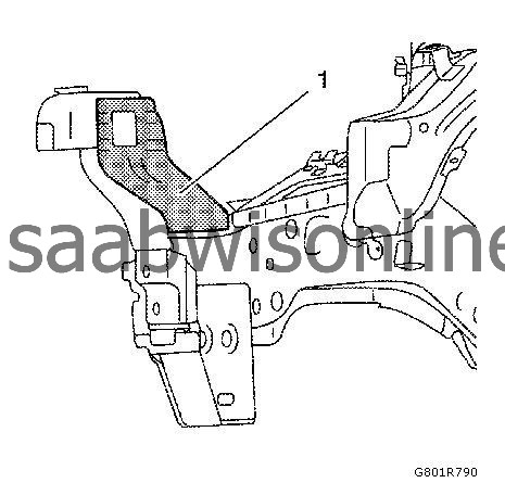
|
|||||||
| 11. |
Remove the front end sheet metal cross panel reinforcement (1).
|
|
| 12. |
Locate and grind out all of the necessary factory welds (1). 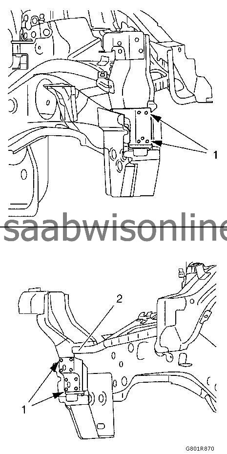
|
|||||||
| 13. |
Remove the structural adhesive (2).
|
|
| 14. |
Locate and drill out all of the necessary factory welds (1). 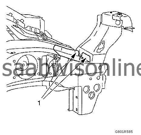
|
|||||||
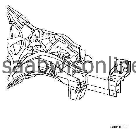
| 15. |
Remove the front end upper tie bar support.
|
|
| Installation Procedure |
| 1. |
Clean and prepare the attaching surfaces for welding.
|
|
| 2. |
Apply bodywork repair through structural adhesive to body (1). Refer to
Structural Adhesive Body Repairs
.
|
|
| 3. |
Clean and prepare the attaching surfaces for welding.
3x slots 8x24 mm (0.3x0.9 in) 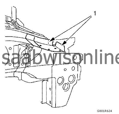
|
|
| 4. |
Position the front end upper tie bar support on the vehicle.
|
|
| 5. |
Verify the fit of the front end upper tie bar support.
|
|
| 6. |
Clamp the front end upper tie bar support into position.
|
|
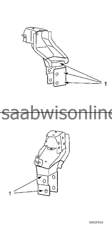
| 7. |
Spot weld (1) the front end upper tie bar support accordingly. 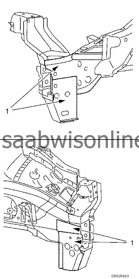
|
|||||||
| 8. |
MIG-braze (1) the front end upper tie bar support.
|
|
| 9. |
Grind MIG brazed seams.
|
|
| 10. |
Position the front end sheet metal cross panel reinforcement (1) on the vehicle.
|
|||||||
| 11. |
Verify the fit of the front end sheet metal cross panel reinforcement (1).
|
|
| 12. |
Clamp the front end sheet metal cross panel reinforcement (1) into position.
|
|
| 13. |
Spot weld the front end sheet metal cross panel reinforcement (1) accordingly.
|
|
| 14. |
Apply the sealers and anti-corrosion materials to the repair area, as necessary. Refer to
Anti-Corrosion Treatment and Repair (Base)
Anti-Corrosion Treatment and Repair (Corrosion Protection)
.
|
|
| 15. |
Install all related panels and components.
|
|
| 16. |
Install the front wheelhouse panel reinforcement.
Front Wheelhouse Panel Reinforcement Replacement
|
|
| 17. |
Install the headlamp mount panel. Refer to
Headlamp Mount Panel Replacement
.
|
|
| 18. |
Install the front end upper tie bar. Refer to
Front End Upper Tie Bar Replacement
.
|
|
| 19. |
Install the headlamp. Refer to
Headlamp Replacement
.
|
|
| 20. |
Connect the negative battery cable. Refer to
Battery Negative Cable Disconnection and Connection
.
|
|
| 21. |
Enable the SIR system. Refer to
SIR Disabling and Enabling
.
|
|
This project is supported by memberships and donations. If you use this site, please consider Joining SCNA and/or making a donation.
Our Friends
