Cylinder Head Replacement - Left Side (LF1 or LFW)
| Cylinder Head Replacement - Left Side (LF1 or LFW) |
Special Tools
EN-45059 Angle MeterFor equivalent regional tools, refer to Special Tools .
| Removal Procedure |
| 1. |
Remove the left bank secondary timing chain. Refer to
Secondary Camshaft Intermediate Drive Chain Replacement - Left Side
.
|
|
| 2. |
Remove the fuel pump. Refer to
Fuel Pump Replacement
.
|
|
| 3. |
Remove the Catalytic Converter. Refer to
Catalytic Converter Replacement - Left Side (LF1)
.
|
|
| 4. |
Remove the oil level indicator tube. Refer to
Oil Level Indicator Tube Replacement (LAU)
Oil Level Indicator Tube Replacement (LF1 or LFW)
.
|
|
| 5. |
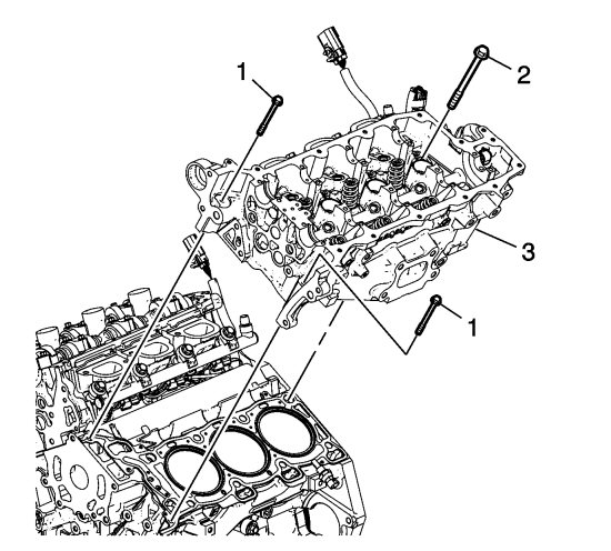
Remove the 2 front M8 left cylinder head bolts (1).

|
|
| 6. |
Remove the left cylinder head bolts (2).
|
|
| 7. |
Remove the left cylinder head (3).
|
|
| 8. |
Remove the ground wire bolt and ground wire.
|
|
| 9. |
Disconnect and reposition harness as necessary.
|
|
| 10. |
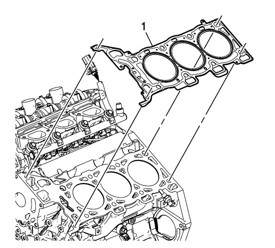
Remove and discard the left cylinder head gasket (1).

|
|
| 11. |
Clean and inspect the cylinder head and the engine block sealing surfaces. Refer to
Cylinder Head Cleaning and Inspection
and
Engine Block Cleaning and Inspection
.
|
|
| 12. |
Transfer parts as needed. Refer to
Cylinder Head Disassemble (LF1, LFW or LFX)
Cylinder Head Disassemble (LAU or LBW)
.
|
|
| Installation Procedure |
| 1. |
Ensure the cylinder head locating pins are securely mounted in the cylinder block deck face.

|
|
| 2. |
Install a NEW left cylinder head gasket (1) using the deck face locating pins for retention.
|
|
| 3. |
Align the left cylinder head (3) with the deck face locating pins.

|
|
| 4. |
Place the left cylinder head in position on the deck face.
|
|
| 5. |
Refer to
Fastener Caution
.
Install the NEW M11 cylinder head bolts (1). 
|
||||||||||
| 5.1. |
Tighten the M11 cylinder head bolts a first pass in sequence to
30 Nm (22 lb ft)
.
|
| 5.2. |
Tighten the M11 cylinder head bolts a second pass in sequence an additional
150 degrees
using the
EN 45059
meter .
|
| 6. |
Install the 2 NEW front M8 left cylinder head bolts (2).
|
|
| 6.1. |
Tighten the M8 cylinder head bolts a first pass in sequence to
15 Nm (11 lb ft)
.
|
| 6.2. |
Tighten the M8 cylinder head bolts a second pass in sequence an additional
75 degrees
using the
EN 45059
meter.
|
| 7. |
Install the left bank secondary timing chain. Refer to
Secondary Camshaft Intermediate Drive Chain Replacement - Left Side
.
|
|
| 8. |
Install the camshaft cover. Refer to
Camshaft Cover Replacement - Left Side (LAU)
Camshaft Cover Replacement - Left Side (LF1 or LFW)
.
|
|
| 9. |
Install the fuel pump. Refer to
Fuel Pump Replacement
.
|
|
| 10. |
Install the generator. Refer to
Generator Replacement (LAU)
Generator Replacement (LF1)
.
|
|
| 11. |
Install the exhaust manifold. Refer to
Catalytic Converter Replacement - Left Side (LF1)
.
|
|
| 12. |
Install the oil level indicator tube. Refer to
Oil Level Indicator Tube Replacement (LAU)
Oil Level Indicator Tube Replacement (LF1 or LFW)
.
|
|


